Motorized Reconfigurable Auxetic Device
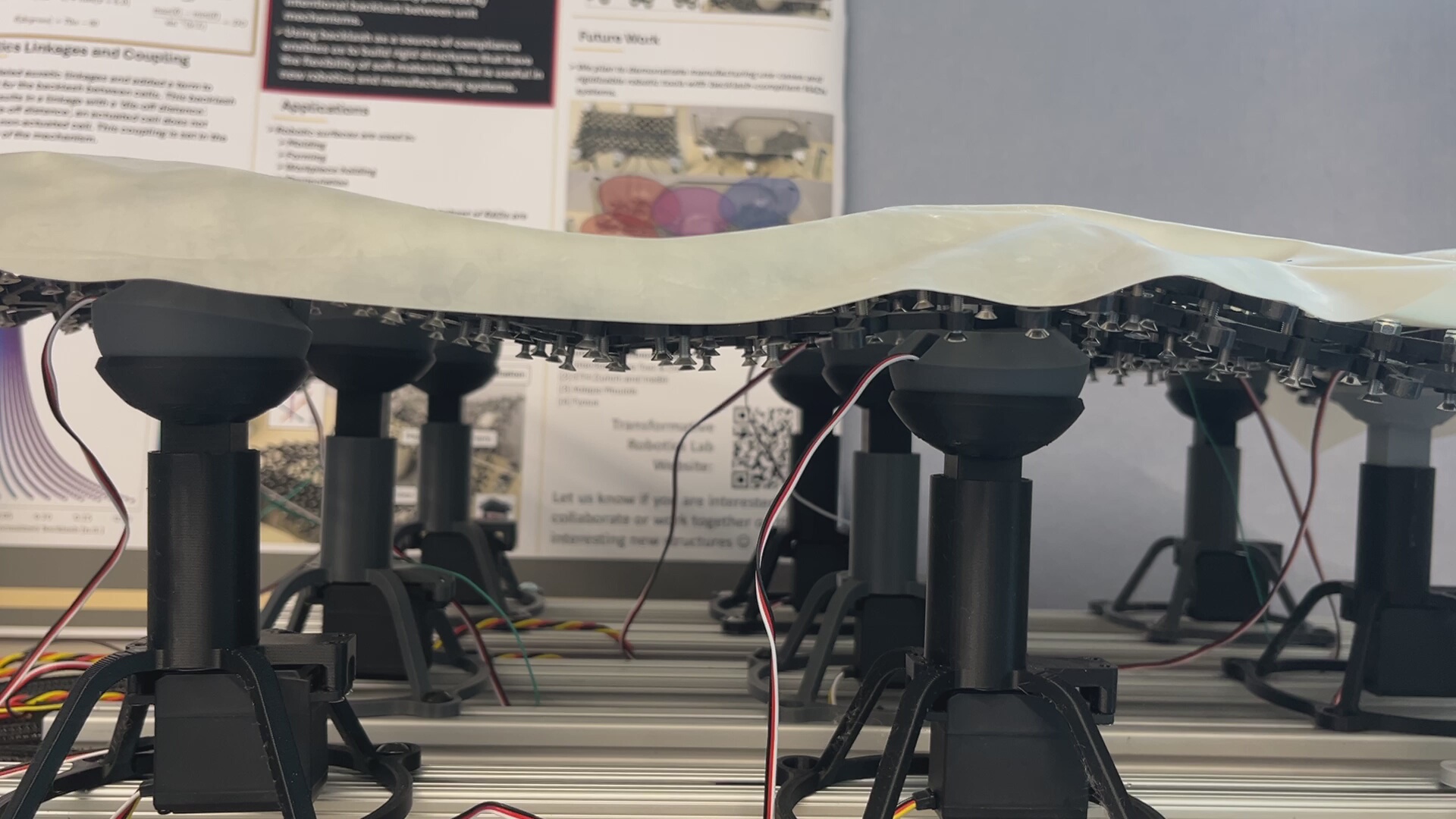
An auxetic material has a negative Poisson’s ratio, meaning it expands sideways when you pull on it instead of necking in. That makes auxetics good at wrapping around curved things, which is why people keep trying to build robotic surfaces out of them. The problem is that most auxetic lattices are baked in at fabrication time.
Reconfigurable Auxetic Devices (RADs) are our attempt at fixing that. The lattice is built from rotating-square auxetic unit cells, and the trick is that the compliance comes from deliberately engineered backlash in the joints rather than from bending flexures. Slop in a mechanism is usually a defect, but here it is the design parameter: it sets how far one cell can rotate before it starts dragging its neighbor along, which sets how localized a shape change can be. Add servos at a handful of cells and you can dial the dilation factor across different regions of one continuous lattice, making the same physical structure hold many different surface shapes.
This is a Transformative Robotics Lab project at Northeastern under Prof. Jeff Lipton. On this project I fabricated and tested lattices, designed the linear actuator modules that drive the surface, and wrote the servo control code.
The governing number is normalized backlash, b/L, the joint slop divided by the cell size. It sets the “die-off distance,” which is how many cells away from an actuated cell you still feel the effect. Our prototype geometry (b/L = 0.1, L = 35 mm) gives a die-off distance of about 32 cells, and pushing normalized backlash from 0.025 up to 0.200 shortens that range monotonically. That is the useful part: you can tune how far an actuator’s influence reaches independently of how big the cells are.
Fabrication mattered more than I expected. Every cell is two concentric printed parts with four joints each, printed on a Prusa MK4 in PLA and held to a 0.1 mm hole tolerance. Since backlash is the design variable, inconsistent backlash is the failure mode, so every part had to be cleaned of residual filament before assembly to get joints that actually behaved the same across the lattice. We built these up to 8x11, 11x15, and 22x5 layouts.
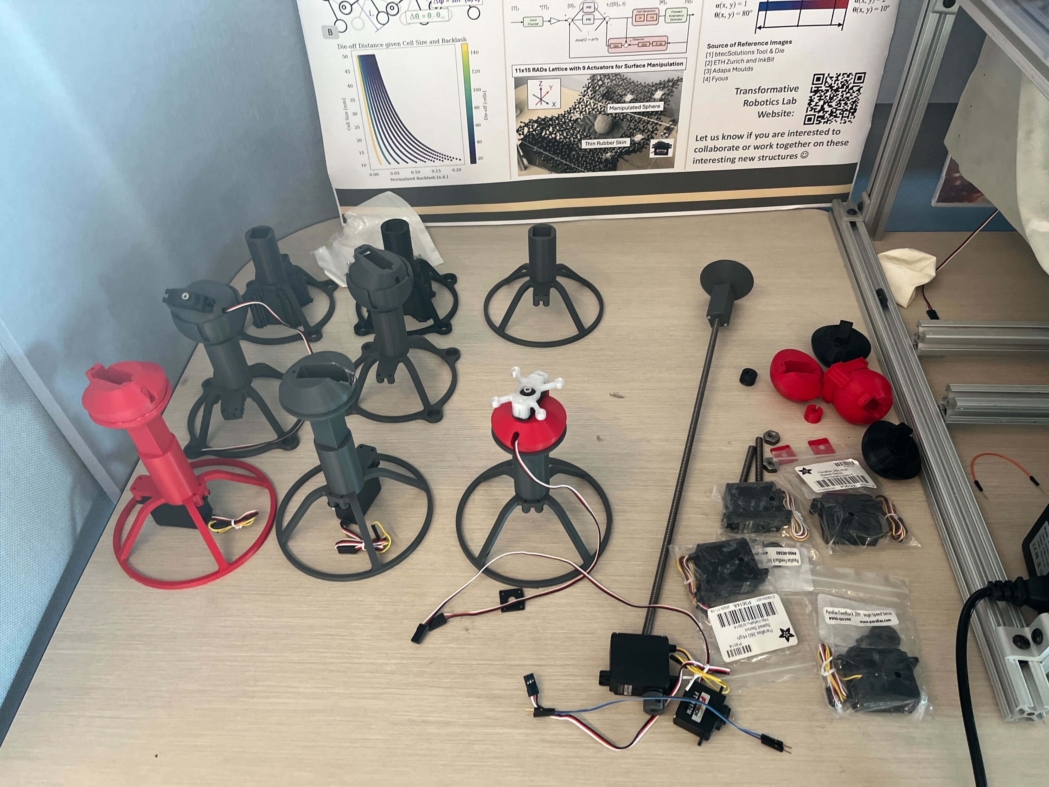
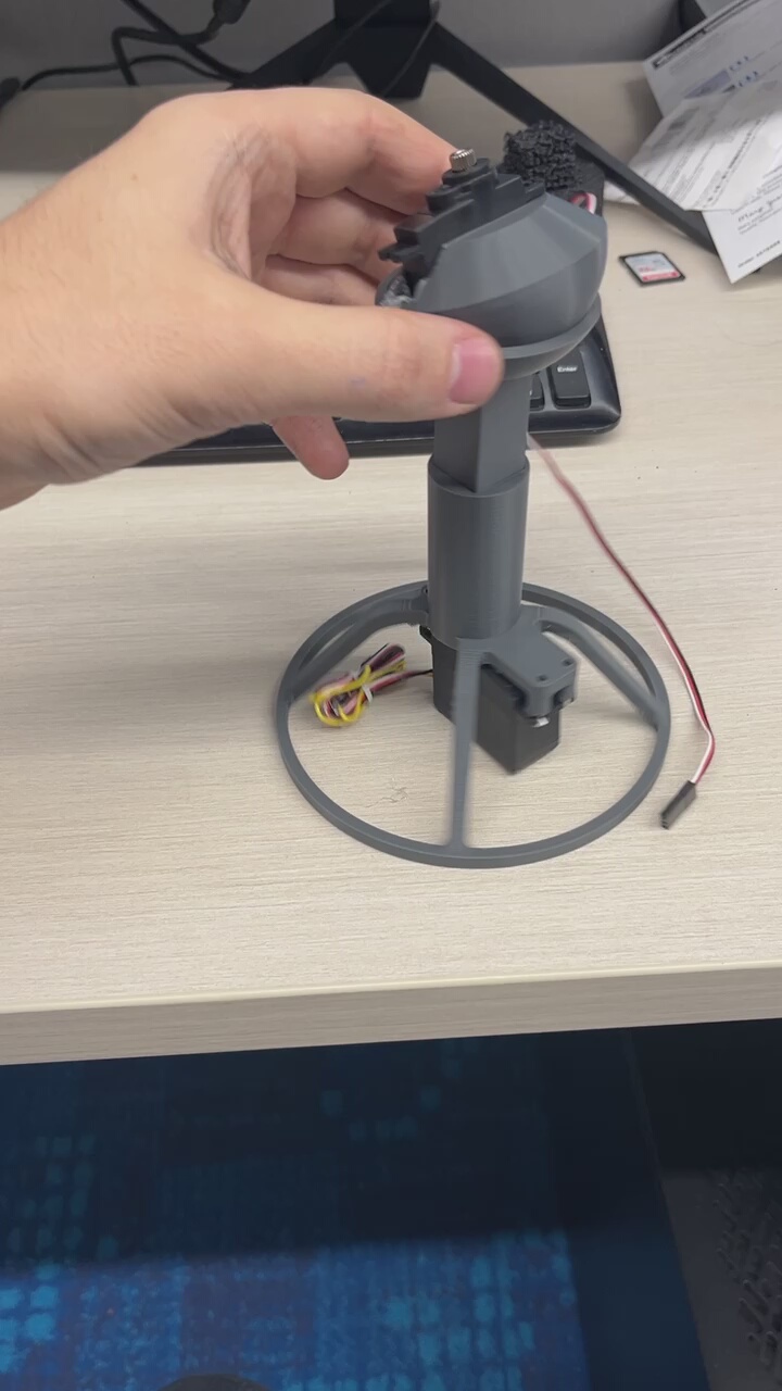
I designed the actuators as self-contained printed modules: a servo in a tripod base driving a telescoping post with a ball head that couples into the lattice above. They went through a revision to improve the ball coupling, and we printed and assembled a set of nine. The base is deliberately sized so the same frame can carry a pneumatic cylinder in place of the servo, which is how the lab wants to drive local inflation and deflation later. I also put together the bill of materials for the linear stages. The modules mount on aluminum extrusion rails, so actuator positions can be rearranged for different lattice sizes.
On the control side, the servos are Parallax Feedback 360 units, which report position back rather than running open loop. All of them hang underneath the lattice so the top surface stays clear and undeformed, with wiring routed below to the driver board and supply. I wrote the servo control code that drives the actuation sequences, and calibrated servo response at 0.1 rad intervals so commanded dilation maps to actual cell rotation. Six servos are enough to put six independent dilation zones across the large lattice, spanning the full range from a fully contracted cell to a fully expanded one.
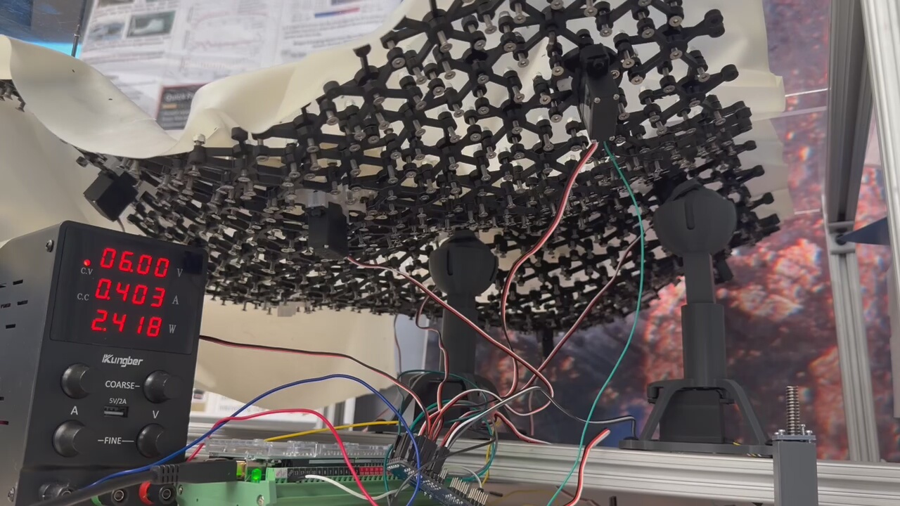
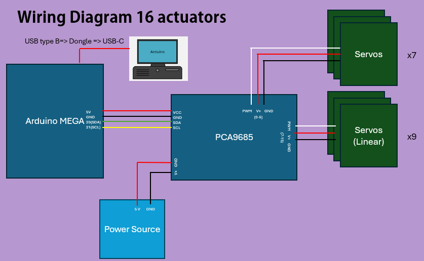
Because a single microcontroller runs out of usable PWM channels fast, the larger build fans out through a PCA9685 PWM driver over I2C from an Arduino MEGA, with the servos on their own supply rather than pulling through the board. That is what scaled the system to sixteen actuators.
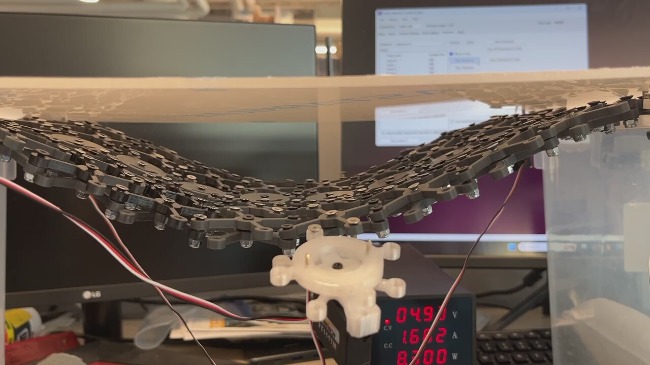
The lattice hangs beneath a clear sheet and is allowed to drape under its own weight, so gravity sets a neutral curvature and the servos work against that baseline. Pulling down at one cell produces a smooth local valley rather than a crease, which is the backlash coupling doing its job across neighboring cells.
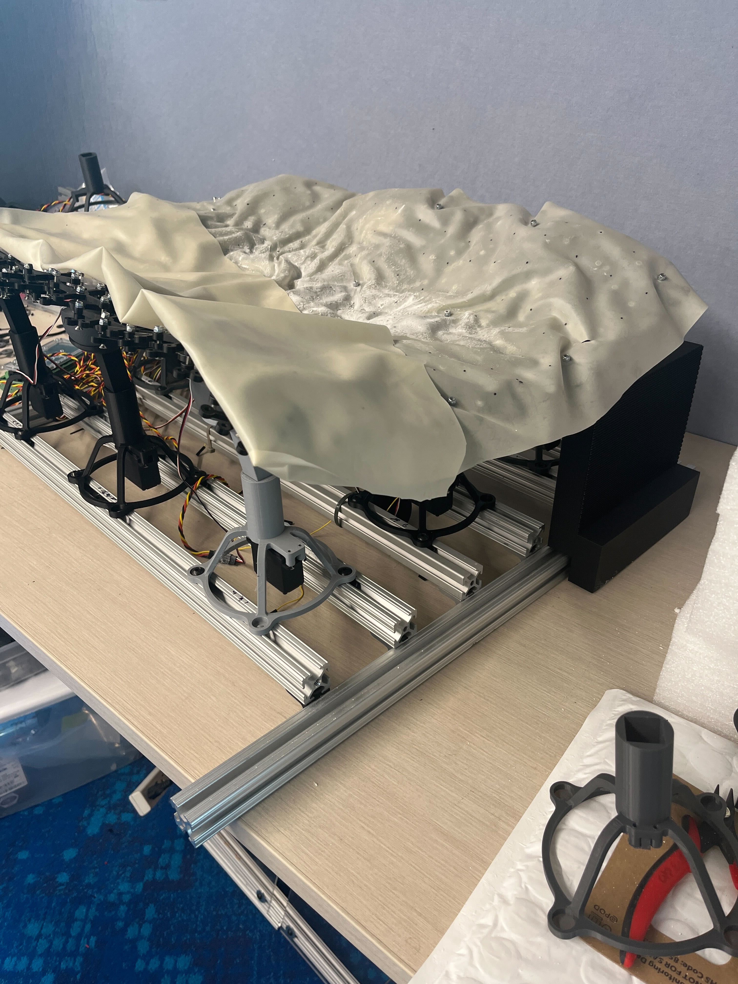
A thin rubber skin goes over the top. It has to stretch through the full range of lattice motion without tearing, and it turns the discrete lattice into a continuous, non-permeable surface that an object can actually sit on.
With mechanical locks instead of servos setting the dilation of selected cells, one lattice can be pinned into a target contour. We conformed lattices to NACA 0018 and NACA 2408 airfoil profiles with height errors under 2% of wing length, and got a 22x5 lattice to hold a blended wing shape with two different airfoil profiles at once along its span. A surface that can be locked into an arbitrary contour and then reset is basically a reprogrammable mold, which is where a lot of the outside interest in this work has come from.
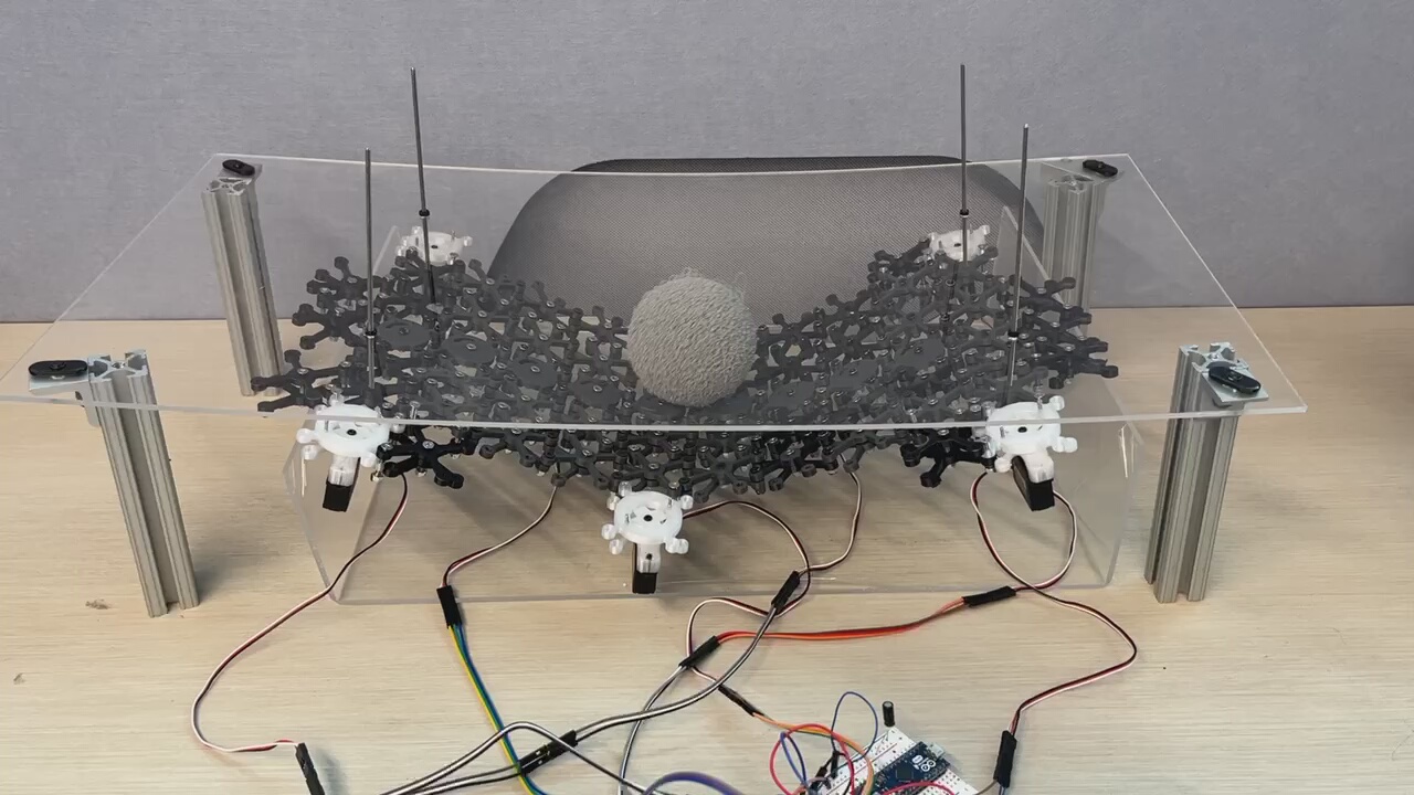
Testing this against a foam ball with optical tracking turned up three distinct regimes. Drive the wave fast enough and it beats static friction and ball inertia, giving repeatable transport, roughly 200 mm along the travel axis over a 20 second window while staying within 50 mm of the centerline. Too slow and the ball just sits there. In between, it creeps to a new equilibrium and stops. The direction of the dilation wave picks the transport axis.
Work with Jacob Miske, Ahyan Maya, Ahnaf Inkiad, and Prof. Jeffrey Lipton, supported by Northeastern’s Institute for Experiential Robotics.