Flat Planar Mechanism
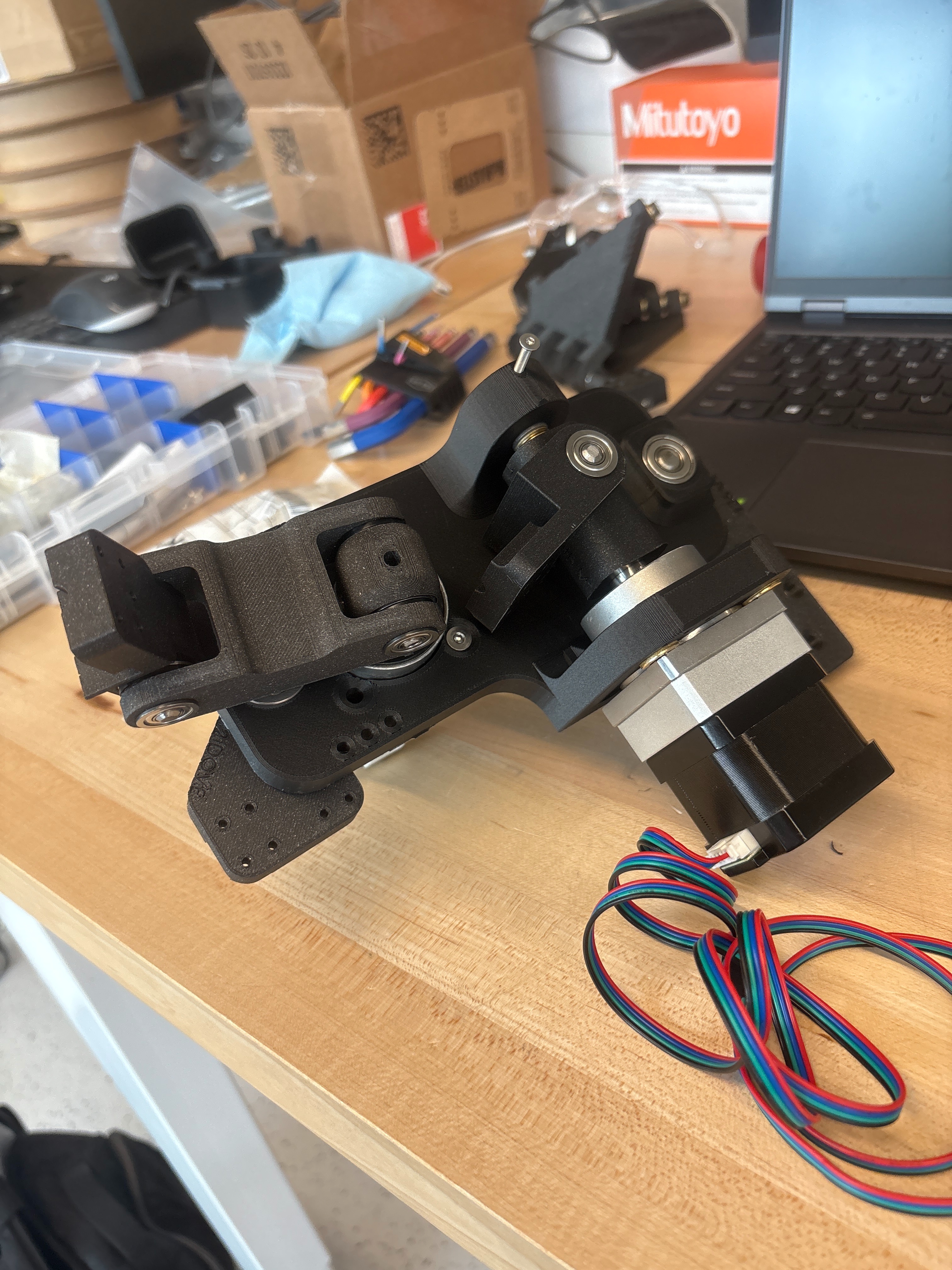
A Flat Plane Mechanism (FPM) is a linkage that gets its flatness from geometry rather than from a precision-ground surface. The linkage constrains one point to move on a sphere, and by the geometric inversion relationship between a sphere and a plane, the tool point at the other end is forced to trace a plane. Because the flatness is encoded in the link lengths themselves rather than in a long chain of machined references, an FPM can hit surprisingly tight planarity without precision-machined parts.
The lab runs two of these machines side by side, and they are built to answer different questions. The Metal FPM is the precision instrument with machined construction, Maxon motors driving the revolute joints through harmonic drives, and the build that gets shown off as a working coordinate measuring machine. The Wood FPM is the cheap one, and it is the one I worked on. Its entire linkage is FFF printed and it runs on stepper motors off a 3D printer control board. It gets its name from the turned wooden dowel it was built to probe, not from the linkage itself. The Metal FPM establishes what the geometry can do when you build it properly, and the Wood FPM asks how much of that survives when the linkage comes off a printer instead of a mill. My work was mostly on the software and firmware side of the Wood and Metal FPM, with some help on the mechanical assembly.
The whole linkage is FFF printed, running on pressed-in ball bearings and sleeve bushings at each joint, and driven by NEMA 17 steppers with integrated encoders. Jake Alpert did the bulk of the mechanical design and build. I helped with assembly and installed the homing sensor for the Y axis, which worked but sat at the wrong spacing and was one of the parts we flagged for a redesign. A lot of the early mechanical iteration was chasing backlash out of the joints with better washers and real bushings, since a printed linkage starts out with a lot more slop than a machined one.
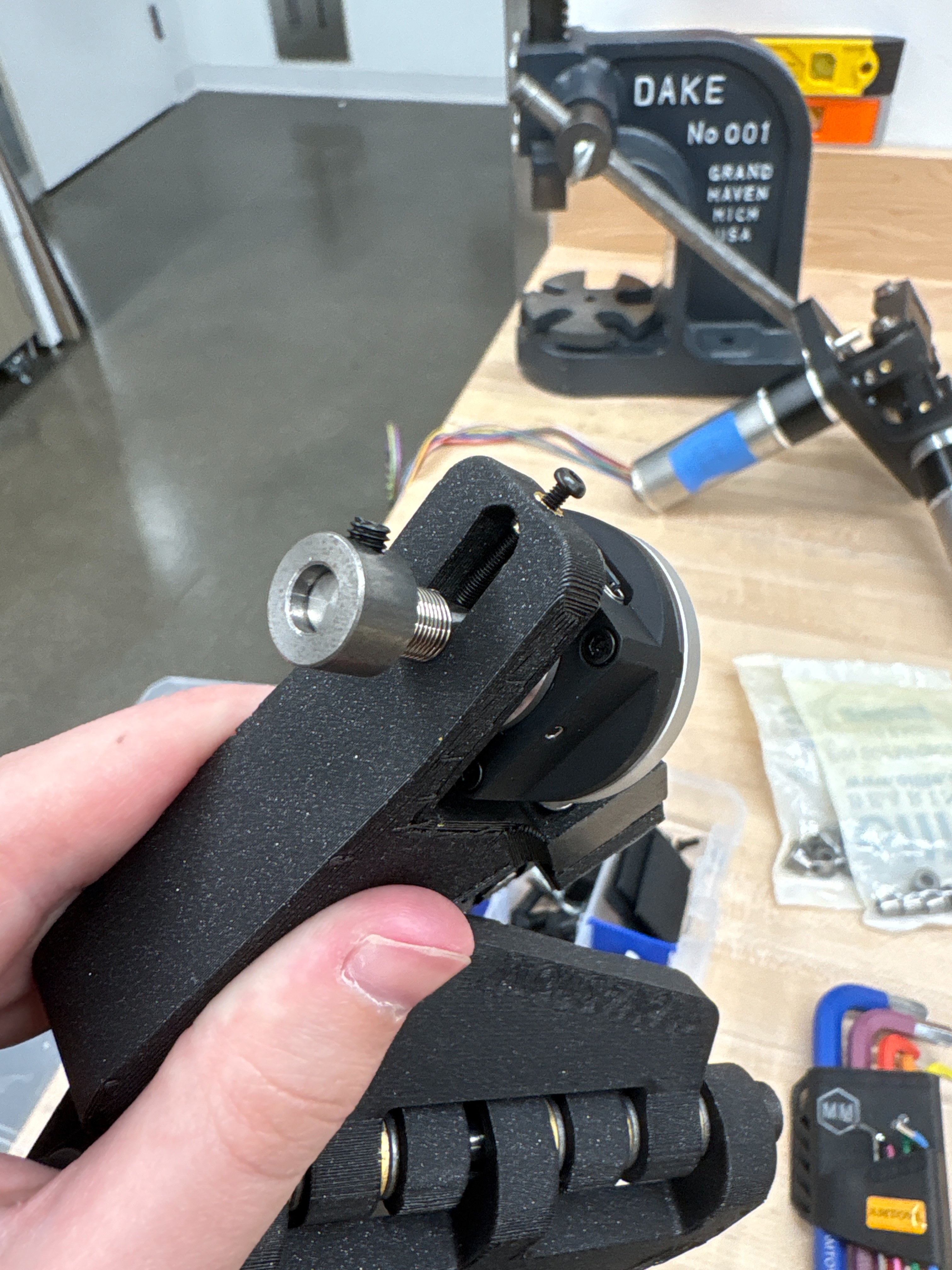
The motion stack runs on a BigTreeTech Octopus board flashed with Marlin, which is convenient because it already handles trapezoidal motion planning, homing, and G38 probing. Adding the rotary A axis is where it got interesting. I developed the firmware and the A-axis inverse kinematics, and I took the Python host control. I worked out the coordinate frame math so that the offset shifts the frame in a way that preserves the tool axes — +x and +y point the same direction regardless of what theta the rotary joint is at, which is what makes a scan path expressible in workpiece coordinates instead of joint coordinates.
While the A-axis firmware was still in progress, I wrote a simulator so the host side could be developed in parallel. FPM-sim models a Marlin-style command loop for a 4-axis machine: it parses G-code, runs trapezoidal motion profiles under per-axis feedrate and acceleration limits, handles homing and probing, and renders the state live in a Three.js browser view. It exposes a Linux PTY, so the real host software talks to the simulator over a virtual serial port exactly the way it talks to the board. That let me write and debug the probing sequences against a fake machine, then point the same script at the real one.
The host software itself is a Python control script and a small web UI that drives the machine over serial. It exposes the scan parameters directly — probe target, probe speed, scan start, Y range, and sample count — and plots every probed contact point as it comes in, so you can watch a surface profile build up in real time and stack repeat passes on the same axes.

The namesake test article is a wooden dowel turned on a toy lathe in the lab, chosen because it gives a real surface with resolvable features. The machine probes along the dowel and records the X contact position at each Y sample.

Repeatability was the number we actually cared about, so I ran the same scan over and over and overlaid the results. Consecutive passes agreed to roughly 0.03 mm at the same sample point, and across 27 repeat scans most of the profile stacked inside a band of a few hundredths of a millimeter, with occasional outlier points where the probe caught an edge. The shape of the profile, including the step around Y = 8 mm, reproduced cleanly every time.

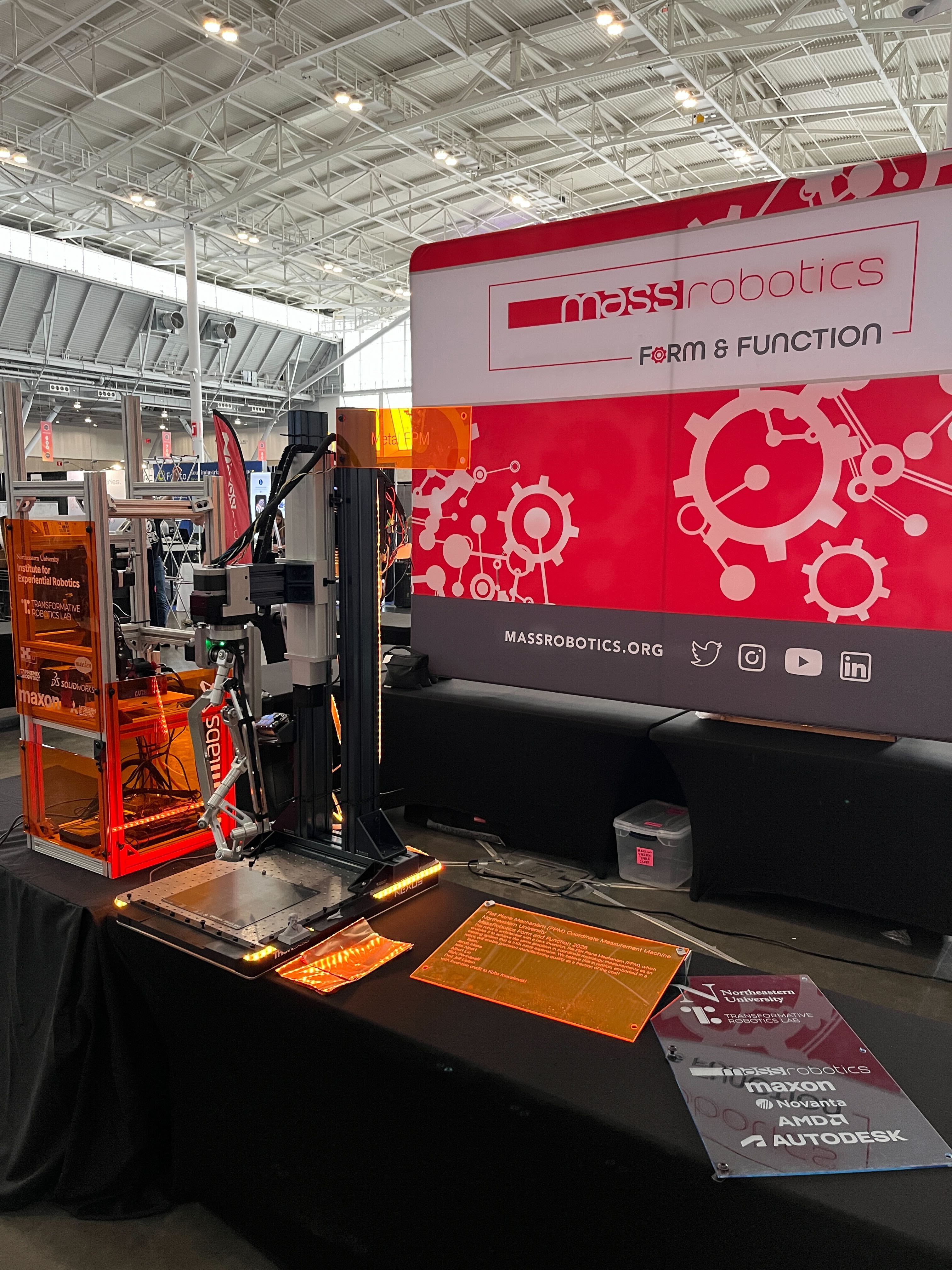
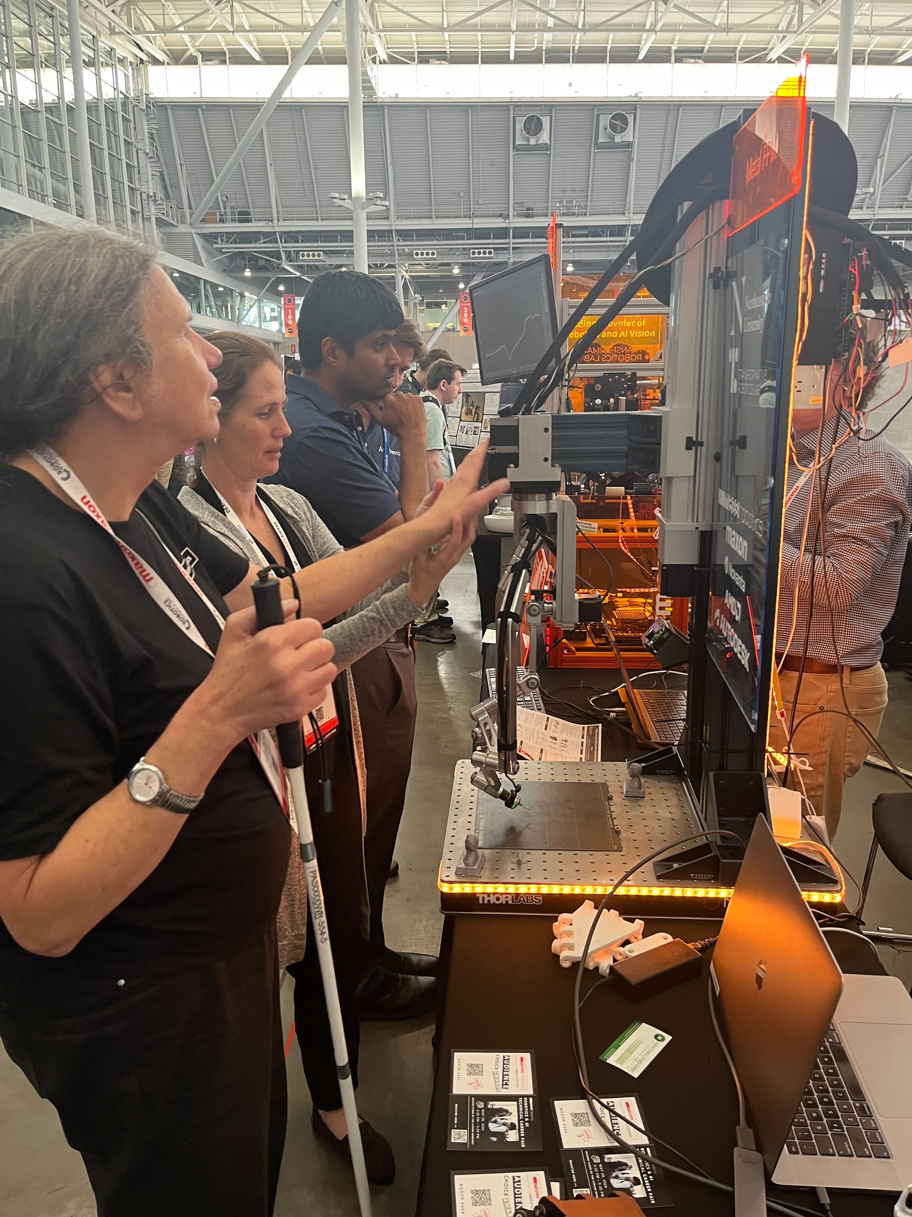
The lab brought both machines to MassRobotics Form and Function 2026. The Metal FPM sat on the optical breadboard as the headline coordinate measuring machine, and we ran live probing demos on the Wood FPM next to it. Explaining to people who had never seen a linkage generate its own reference plane why the printed one works at all was a good test of whether I actually understood it.
This was a group effort with specific credit to Jacob Miski and Jake Alpert in the Transformative Robotics Lab under Prof. Jeff Lipton.